How to Install a 110 Wiring Block
By: CableOrganizer®
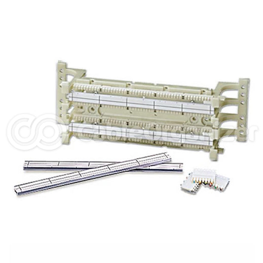
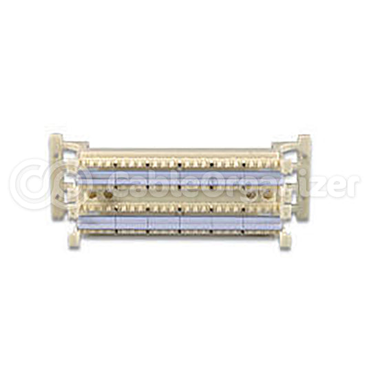
A 110 wiring block is a crucial telecommunications and networking component that organizes and terminates copper wiring for voice and data applications. It was initially developed in the late 20th century to facilitate twisted pair wire terminations in telephone cables. Since it was created, the 110 wiring block has also been adapted for use in Ethernet networking applications. It can now oftentimes be generically known as a "110-style wiring block." These two terms are usually interchangeable though the 110-style wiring block may be a broader category with variations and enhancements that the original 110 wiring block models do not have, such as density, ease of use, and specific networking standards compatibility. The 110-style wiring block is however, typically compatible with the tools and accessories that have been used with the 110 wiring block. But the compatibility can be dependent on the specific product and its design. The wires in either setup are punched down in groups of 50 pairs into a grid-style pattern, creating organized and reliable structured cabling systems. Twisted pair wires in the block are systematically color-coded, like the T568B wiring scheme. Wires then need to be grouped and arranged based on the wiring scheme used, whether that is T568A or T568B. The T568B standard is mainly preferred within the United States for new networks, with T568A more frequently used for older residential systems, and U.S. government installations. However, the choice of one or the other may be on a case-by-case basis, dependent on the installation and local practices. Explore more of the differences here between the T568A and T568B standards.
General directions to install a 110-style wiring block are below. Specific procedures may vary depending on the product manufacturer.
STEP 1:
Choose a suitable mounting surface for the 110 wiring block. The surface is dependent on whether the block is a wallmount or rackmount style.
It is best to clean the surface prior to attaching the 110-style wiring block to it. Cleaning products used should be based on the manufacturer’s recommendations. Common methods include using a lint-free cloth or soft brush, applying a mild cleaning solution, sanitizing the surface with isopropyl alcohol (rubbing alcohol), or rubbing on an antistatic cleaner if the environment tends to build up static electricity.
Take the mounting brackets, screws, and other necessary hardware required, then affix the block to the surface.


STEP 2:

With some methods, cable ends need to be stripped for the application. If this is the method chosen, use a wire stripper to remove the outer insulation of the cable jacket, which makes the individual wires visible. Only strip as much as required per the manufacturer recommendations for the block being used, to ensure the conductors are properly terminated.
After wires are stripped, they need to be trimmed with a cutting tool.
Choose the wiring standard you plan to use, whether it is the T568A or T568B and arrange wires in the appropriate order.
Should the wire stripping method not be used, all wires onto the 110-style wiring block should be placed into the corresponding IDC (Insulation Displacement Connection), securing and seating the connections with a punchdown tool. An IDC establishes a connection without removing wire insulation.
A punchdown tool is additionally used if the traditional wire stripping method is performed on the wires before they are placed into the 110 wiring block.


STEP 3:

Identify the connections on the block using a label printer to mark them for future maintenance and replacement.
Verify connections have been made with a cable tester after wires have been installed onto the block.
Shop for 110-style wiring blocks here.