Skip to content
Network Wiring Instructions
By: CableOrganizer®

RJ-11 (TELEPHONE) PLUG
Figure 1 is the wiring scheme for the plug side of an RJ-11 connector. The diagram is shown with the "hook clip" on the underside. The typical RJ-11 connector has six terminals. Usually, only the middle four pins are used. The POTS (Plain Old Telephone Service) residential telephone wiring generally contains two pairs of wires — designed for two separate telephone lines. The center pins (Red and Green) contain the first telephone line. Please note that business phone systems may be wired differently.

RJ-45 (DATA) PLUG WIRING
Figure 2 is the wiring scheme for the plug side of an RJ-45 connector in accordance with T-568B standards. The T-568B standard is the most used. The wiring diagram is shown with the "hook clip" on the underside. The wall jack may be wired in a different sequence because the wires may be crossed inside the jack. The jack should have a wiring diagram or designated pin numbers/colors to match up to the color code below. When wiring a jack or an RJ-45 plug, remember to keep the “twist” as close as possible to the (jack or plug) receptacle. This will ensure compliance with Ethernet wiring standards.
SPECIFICATION T-568B
| PIN # | COLOR | PAIR # | NAME |
|---|---|---|---|
| 1 | white/orange | 2 | Transmit Data + |
| 2 | orange | 2 | Transmit Data - |
| 3 | white/ green | 3 | Receive Data + |
| 4 | blue | 1 | not used |
| 5 | white/ blue | 1 | not used |
| 6 | green | 3 | Receive Data - |
| 7 | white/ brown | 4 | not used |
| 8 | brown | 4 | not used |

(Even pin numbers are always solid color. Odd pin numbers are white/ stripe color.)
For reference purposes only, the chart below details the wiring scheme according to T-568A standards. Be sure adhere to EITHER the T-568B or the T-568A standard. Do not mix different wiring specifications within the same wiring installation.
SPECIFICATION T-568A
| PIN # | COLOR | PAIR # | NAME |
|---|---|---|---|
| 1 | white/ green | 3 | Receive Data + |
| 2 | green | 3 | Receive Data - |
| 3 | white/ orange | 2 | Transmit Data + |
| 4 | blue | 1 | not used |
| 5 | white/ blue | 1 | not used |
| 6 | orange | 2 | Transmit Data - |
| 7 | white/ brown | 4 | not used |
| 8 | brown | 4 | not used |
CROSSOVER CABLE
Some applications may require a crossover cable. The most common use of a crossover cable occurs in wiring together two Hubs. A crossover cable “crosses over” Transmit and Receive Data. Pins 1 and 3 are crossed over, and Pins 2 and 6 are crossed over. To build a CROSSOVER cable, simply wire one side according to specification T-568B and wire the other side according to T-568A.
110 BLOCK / 66 BLOCK PUNCHDOWN
Punchdowns are made with the pairs in order with the white-stripe wire first, then the colored wire.
- Pair 1 white/blue - Blue
- Pair 2 white/orange - Orange
- Pair 3 white/green - Green
- Pair 4 white/brown – Brown
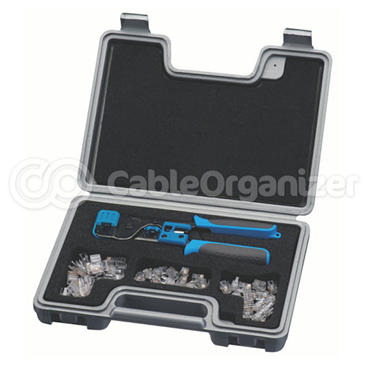
Be sure to purchase an all-in-one tool that cuts, strips and terminates the ends of RJ11 and RJ45 cables.
Reminder hint: BLOG– BLue Orange Green and Brown
Are you looking to increase your data transfer speeds? Shop at CableOrganizer® for Cat6 and Cat6a Cables, plugs and other items.